Introduction
Turbines using the impulse action of water are the best ones. No it’s not like that reaction turbines are more efficient, when all of this was happening, James B. Francis, an American civil engineer comes up with his turbine called Francis turbine. What’s different he is doing!!!
He is just mixing them up. The good’s of both the impulse and reaction turbine, say water enters the turbine radially and exits axially. But that’s not a secret to his turbine efficiency. The magic lies in his amazing design of blades, these blades rotate using both reaction and impulse force of water flowing through them.
The ability of francis turbine to use both the kinetic and potential energy to produce power, shorts out a major problem of water head availability as it could be used efficiently for head as low as 50m to as high as 400m and also for a wide range of flow rates which could be as low as 10 meter-cube per second to as high as 700 meter-cube per second.
That’s why Francis turbine is also called as mixed flow turbine. so it is now obvious that it is the best modern turbine we have till date. It is the most widely used turbine in the hydro-power plants. So let’s just figure it out what else it contains which makes it stand out of league of all other turbines.
Working Principle
Francis turbine blades are designed in such a way that one portion of the blade design creates the pressure difference between the opposite faces of the blade when water flows through it, and the remaining portion’s blade design use the impulse force of water hitting it and this combined action of pressure difference and impulse force generates enough power to get turbine moving at a required speed. Thus there would be a decrease in both kinetic energy and potential energy of water at exit, then what it has when it enters the turbine.
It is a clever design which uses both the reaction and impulse force to generate power output better than individual impulse turbine or reaction turbines could produce at same water head conditions.
Also Read:
Pelton Turbine Working, Main Parts, Application with Diagram
Difference Between Impulse and Reaction Turbine
Types of Wind Turbines – Horizontal Axis and Vertical Axis Wind Turbines
Main Components
The Various main components of francis turbine are:

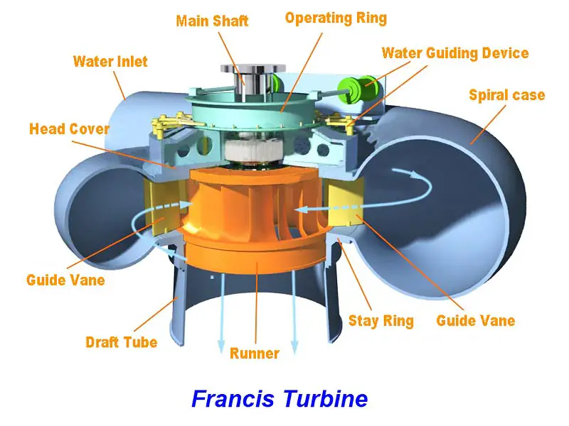
1. Spiral casing
It is a spiral casing, with uniformly decreasing cross- section area, along the circumference. Its decreasing cross-section area makes sure that we have a uniform velocity of the water striking the runner blades, as we have openings for water flow in-to the runner blades from the very starting of the casing, so flow rate would decrease as it travels along the casing. So we reduce its cross-section area along its circumference to make pressure uniform, thus uniform momentum or velocity striking the runner blades.
2. Stay vanes
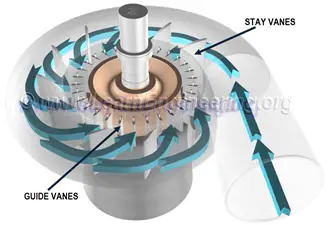
Stay vanes and guide vanes guides the water to the runner blades. Stay vanes remain stationary at their position and reduces the swirling of water due to radial flow, as it enters the runner blades. Thus making turbine more efficient.

3. Guide vanes
Water after passing through stay vanes, glides through guide vanes to enter the runner blades. Guide vanes can change their angle thus can control the angle of attack of water to the runner blades, making them work more efficiently. Moreover they also regulate the flow rate of water into the runner blades thus controlling the power output of a turbine according to the load on the turbine.
4. Runner blades
Design of the runner blades decides how well a turbine is going to perform. So runner blades of mixed flow turbine can be divided into two parts, the upper part of the blades use the reaction force of water flowing through it and the lower half is in the shape of a small bucket using the impulse action of water flowing through it. These two forces together makes the runner to rotate.
5. Draft tube
Draft tube connects the runner exit to the tail race. Its cross-section area increases along its length, as the water coming out of runner blades is at considerably low pressure, so its expanding cross-section area help it to recover the pressure as it flows towards tail race.
Working of Francis Turbine
Water enters the turbine through spiral casing, and starts entering the runner blades, passing through stay vanes and guide vanes, as it moves along the length of casing the decreasing cross-section area of the spiral casing makes sure that the pressure energy of water would remain uniform along its length, as a portion of water is also entering the runner blades, which would reduce its flow rate along the length of the casing. The stay vanes being stationary at their place, removes the swirls from the water, which are generated due to flow through spiral casing and tries it to make the flow of water more linear to be deflected by adjustable guide vanes. The angle of guide vanes decides the angle of attack of water at the runner blades thus make sure the output of the turbine. Guide vanes also controls the flow rate of water in-to the runner blades thus acting according the load on the turbine. The runner blades are stationary and can-not pitch or change their angle so it’s all about the guide vanes which controls the power output of a turbine.
Further-more the upper part of runner blades are designed in such a way that they use the pressure difference between the opposite faces of a blade created by water flowing through it, same as the air-foil uses the pressure difference to generate lift force. And the remaining part of the blade is designed like a small bucket, which makes use of water’s kinetic energy. Thus runner blades make use of both pressure energy and kinetic energy of water and rotates the runner in most efficient way.
The water coming out of runner blades would lack both the kinetic energy and pressure energy, so we use the draft tube to recover the pressure as it advances towards tail race, but still we cannot recover the pressure to that extent that we can stop air to enter into the runner housing thus causing cavitation.
Also Read:
Closed Cycle Gas Turbine: Construction, Working, diagram
For better comprehension watch the video given below:
What is Cavitation?
Difference in the pressure of water entering the turbine and that exists after striking the runner blades is too high, due to this pressure difference the air molecules which are relatively at high pressure then water coming out, enters the turbine casing in the form of bubbles. These bubble keeps on exploding near the surface of the runner blades continuously causing a shock wave, which produces a kind of defect at runners surface called cavitation, thus causing a serious problem for turbines efficiency. So what can we do is to prevent blades from cavitation? One solution is to use a really hard surface material like stainless steel or we can also go with surface Hardening of the runner blades, to prevent them from cavitation.
Applications
- Francis turbine is the most widely used turbine in hydro-power plants to generate electricity.
- Mixed flow turbine is also used in irrigation water pumping sets to pump water from ground for irrigation.
- It is efficient over a wide range of water head and flow rate.
- It is most efficient hydro-turbine we have till date.

Very quickly this website will be famous amid all blog people, due to it’s good content|