Introduction
We always discuss “The air fuel mixture combust to cause the movement of the piston which in turn causes crankshaft rotation” also “The residual of the combustion goes out from the exhaust” but have you ever wonder, How does this intake and exhaust occurs?, How the timing of this intake and exhaust is controlled? The answer is intake and exhaust valve, right? But the question arises, How these intake and exhaust valve is controlled? Let’s just dig it out.
A valve timing diagram is a graphical representation of the opening and closing of the intake and exhaust valve of the engine, The opening and closing of the valves of the engine depend upon the movement of piston from TDC to BDC, This relation between piston and valves is controlled by setting a graphical representation between these two, which is known as valve timing diagram.
The valve timing diagram comprises of a 360 degree figure which represents the movement of the piston from TDC to BDC in all the strokes of the engine cycle, Which is measured in degrees and the opening and closing of the valves is controlled according to these degrees.
Why do We Need Valve Timing diagram?

The normal engine completes around 100,000 cycles per minute, as we know there are number of processes involved in a single cycle (from the intake of the air-fuel mixture to the exhaust of the combustion residual) of an internal which makes it necessary to be equipped with an effective system that can enable
- Synchronization between the steps of a cycle of the engine from the intake of air-fuel ratio to the exhaust of the combustion residual.
- Complete seizure of the combustion chamber at the instant at which the combustion of air-fuel mixture takes place as the leakage can cause damage to the engine and can be hazardous.
- Provide engine with a mixed air and fuel or air in case of diesel engine when required ( at the time of suction) which is the necessity of the engine.
- Provide the exit for the combustion residual so that the next cycle of the engine can take place.
- Ideal timing for the opening and closing of the inlet and outlet valve which in turn protect the engine from defects like knocking or detonation.
- A high compression ratio required to combust the fuel especially in case of diesel engine by overlapping the closing of the valve.
- The cleaning of engine cylinder which in turn maintain the quality of combustion and decreases wear and tear inside the cylinder.
- The study of the details of the combustion that is required for the modification of the power of the engine.
So due to these reasons a engine weather it is 2-stroke or 4-stroke is designed according to the valve timing diagram, so that the movement of piston from TDC to BDC is provided with the ideal timing of opening and closing of the intake and exhaust valves respectively.
Also Read:
- What is Gear Ratio in Transmission System?
- How Automatic Transmission Works? – Best Explanation Ever
- Torque Converter Working, Principle, Main Parts and Application
Valve Timing Diagram for 4-Stroke Engine (Petrol and Diesel)
As we all know in 4-stroke engine the cycle completes in 4-strokes that are suction, compression, expansion and exhaust , The relation between the valves (inlet and outlet) and piston movement from TDC to BDC is represented by the graph known as valve timing diagram.
Theoretical

1. Suction Stroke- The engine cycle starts with this stroke, Inlet valve opens as the piston which is at TDC starts moving towards BDC and the air-fuel mixture in case of petrol and fresh air in case of diesel engine starts entering the cylinder,till the piston moves to BDC.
2. Compression Stroke- After the suction stroke the piston again starts moving from BDC to TDC in order to compress the air-fuel (petrol engine) and fresh air (diesel engine) which in turn raises the pressure inside the cylinder which is essential for the combustion of the fuel.
- The inlet valve closes during this operation to provide seizure of the chamber for the compression of the fuel.
3. Expansion Stroke- After compressing the fuel, The combustion of the fuel takes place which in turn pushes the piston which is at TDC towards BDC in order to release the pressure developed by the combustion and output is obtained .
Note – In petrol engine combustion takes place due to the spark produced by the spark plug.
- In petrol engine the air and fuel charge enters the cylinder during suction stroke.
- In diesel engine combustion occurs due to the high compression provided by the compression stroke which is responsible for raising the temperature inside cylinder upto auto-ignition temperature of the diesel and air charge.
- In diesel engine the fresh air enters inside the cylinder during suction stroke and the fuel is sprayed by the fuel injectors over the air.
4. Exhaust Stroke- After expansion stroke the piston which is at BDC starts moving towards TDC followed by the opening of exhaust valve for the removal of the combustion residual
- Exhaust valve closes after the piston reaches TDC.
Actual or Practical Process


- In suction stroke of 4-stroke engine the inlet valve opens 10-20 degree advance to TDC for the proper intake of air-fuel(petrol) or air (diesel) ,which also provides cleaning of remaining combustion residuals in the combustion chamber.
- When the piston reaches BDC the compression stroke starts and again the piston starts moving towards TDC , The inlet valve closes 25-30 degree past the BDC during the compression stroke, which provide complete seizure of the combustion chamber for the compression of air-fuel (petrol engine) and air (diesel engine).
- During the compression stroke as the piston moves towards TDC , the combustion of fuel takes place 20-35 degree before TDC which provides the proper combustion of fuel and proper propagation of flame.
- The expansion strokes start due to the combustion of fuel which in turn releases the pressure inside the combustion chamber and provide rotation to the crankshaft, The piston moves from TDC to BDC during expansion stroke which continuous 30-50 degree before BDC.
- The exhaust valve opens 30-50 degree before BDC which in turn starts the exhaust stroke and the exhaust of the combustion residual takes place with movement of the piston from BDC toTDC which continues till the 10-20 degree after the piston reaches TDC.
As we can see in the entire cycle of engine valves overlap 2 times i.e. closing of both valves during the compression stroke and opening of both valves during the exhaust stroke.
- How does a Four Stroke Diesel Engine (Compression Ignition Engine) Work?
- What is Two Stroke Engine?
- What is Four Stroke Engine?
Port Timing Diagram for 2-Stroke Engine
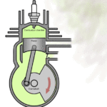
In 2-stroke petrol engine as we all know the engine cycle completes in 2-strokes i.e expansion stroke and compression stroke, The fuel intake and combustion residual exhaust occurs respectively during these 2 strokes.
Theoretical valve timing
Expansion stroke-
At the beginning of the expansion stroke the piston which is at TDC starts moving towards BDC due to the combustion of compressed air-fuel (petrol engine) and (diesel sprayed charge in diesel engine) during compression stroke and the power output is obtained.
- The air-fuel(petrol engine) and air (diesel diesel) enters through the inlet port during the expansion strokes as the piston moves from TDC to BDC during this stroke.
- The expansion stroke continuous till the piston reaches BDC.
Compression Stroke-
At the end of the expansion stroke, the piston which is at BDC starts moving towards TDC and the compression of air-fuel (petrol engine) and diesel sprayed charge (diesel engine) starts along with the exhaust of combustion residual through exhaust port due to the movement of the piston from BDC to TDC.
- The piston closes both inlet port and exhaust port due to its movement from BDC to TDC which in turn raises the pressure inside the combustion chamber.
- At the end of the compression stroke i.e. when the piston reaches TDC combustion of the air-fuel (petrol engine) due to spark and diesel sprayed charge (diesel engine) due to the high pressure takes place, And the cycle repeats again.
Actual or Practical Process


- Before the expansion stroke i.e. completion of the compression stroke, the inlet port open 10-20 degree before the piston reaches the TDC which in turn starts the expansion stroke due to the combustion of air-fuel (petrol engine) from the crankcase and air (diesel engine) entered from the inlet port which in turn pushes the piston towards BDC.
- The inlet port closes 15-20 degree after TDC during the expansion stroke of the 2-stroke engine.
- Due to the movement of piston from TDC to BDC during expansion stroke exhaust port opens 35-60 degree before the piston reaches BDC which in turn starts the exhaust of the combustion residual.
- Transfer port open 30-45 degree before BDC for scavenging process.
- When the piston moves towards TDC from BDC the transfer port closes 30-45 degree after BDC which in turn stops the scavenging process.
- During the movement of piston from BDC to TDC exhaust valve closes 35-60 degree after BDC which seizes the combustion chamber and pressure inside the combustion chamber increases due to the start of compression stroke. and the cycle starts again.
- The air fuel mixture (petrol engine) and air ( diesel engine) is transported to the cylinder during the opening of the transfer port.
Note – The opening and closing of valves few degrees before TDC and BDC is required for normal working of the engine as this degree gaps provides proper completion of the operation of strokes and prevents the engine from defects like knocking, and also causes less emission.
- For power modification this valve timing is adjusted which in turn increases the power and torque of the engine but decreases the economy.
Conclusion
In this article, we have learnt about valve timing diagram of two stroke and four stroke petrol and diesel engine. I hope you have understood it clearly. If you like this piece of information valuable and useful then don’t forget to share it.


