A centrifugal pump is one of the most widely used mechanical devices for transporting fluids in industries, homes, and infrastructure systems. It works by converting mechanical energy into hydraulic energy using centrifugal force generated by a rotating impeller. These pumps are essential in applications such as water supply systems, irrigation, chemical processing, and power plants.
Understanding how a centrifugal pump works is crucial for engineers, technicians, and anyone involved in fluid handling systems. Its simple design, efficient performance, and ability to handle large volumes of liquids make it a preferred choice across industries worldwide. This guide explains the working principle, main components, and practical applications in a clear and practical manner.
What is a Centrifugal Pump?
A centrifugal pump is a hydraulic machine designed to move liquids by increasing their pressure using rotational energy. The pump uses an impeller to accelerate the fluid outward from the center of rotation, creating a flow.
Working Principle of Centrifugal Pump

The working principle of a centrifugal pump is based on the concept of centrifugal force.
Step-by-Step Working:
- The pump is initially filled with liquid (called priming).
- When the impeller rotates, it creates centrifugal force.
- This force pushes the liquid from the center (eye of the impeller) to the outer edges.
- As liquid moves outward, pressure increases.
- The high-pressure liquid is discharged through the outlet pipe.
- A low-pressure region is created at the center, which continuously draws more liquid into the pump.
Key Concept:
- Mechanical energy → Converted into → Pressure energy of fluid
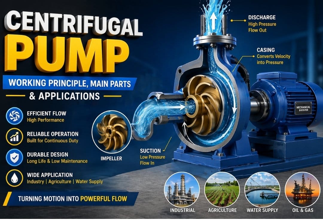
Main Parts of a Centrifugal Pump
1. Impeller
The impeller is the rotating component responsible for transferring energy to the fluid. It consists of curved blades and is usually made of metal or plastic.
2. Casing
The casing surrounds the impeller and helps convert velocity energy into pressure energy. Common types include:
- Volute casing
- Diffuser casing
3. Suction Pipe
This pipe connects the fluid source to the pump inlet. It includes:
- Foot valve (prevents backflow)
- Strainer (filters debris)
4. Delivery Pipe
This pipe carries the fluid from the pump to the desired location.
5. Shaft
The shaft connects the impeller to the motor and transmits rotational motion.
6. Bearings
Bearings support the shaft and reduce friction during rotation.
7. Mechanical Seal
It prevents leakage of fluid along the shaft.
Also Read:
- Positive Displacement Pump: Types, Working, Advantages & Applications Explained
- Reciprocating Pump – Main Parts, Types, Working, Advantages, Disadvantages with Application
- What is Positive Displacement Pump – Definition, Types and Working?
Types of Centrifugal Pumps
Centrifugal pumps are classified in several ways depending on how they operate, their construction, and their application. Understanding these types helps in selecting the right pump for specific industrial or domestic needs.
Based on Flow Direction
1. Radial Flow Pump
In a radial flow pump, the liquid enters the impeller axially (parallel to the shaft) and is discharged radially (perpendicular to the shaft).
Key Features:
- High pressure, low flow rate
- Most commonly used centrifugal pump type
- Suitable for applications requiring high head
Applications:
- Boiler feed systems
- Water supply in high-rise buildings
- Industrial pressure systems
2. Axial Flow Pump
In axial flow pumps, the fluid flows parallel to the pump shaft, similar to a propeller.
Key Features:
- Low pressure, very high flow rate
- Works like a fan or propeller
- Efficient for moving large volumes of liquid
Applications:
- Flood control systems
- Irrigation and drainage
- Cooling water circulation
3. Mixed Flow Pump
Mixed flow pumps combine both radial and axial flow characteristics. The liquid exits the impeller at an angle.
Key Features:
- Moderate pressure and flow rate
- Balanced performance between radial and axial pumps
Applications:
- Agricultural irrigation
- Municipal water systems
- Industrial fluid transfer
Based on Number of Stages
1. Single-Stage Pump
A single-stage pump has only one impeller.
Key Features:
- Simple construction
- Easy maintenance
- Suitable for low to medium pressure applications
Applications:
- Domestic water supply
- Small industries
- Firefighting systems
2. Multi-Stage Pump
A multi-stage pump contains two or more impellers connected in series.
Key Features:
- Generates very high pressure
- Each stage increases fluid pressure
- More complex design
Applications:
- Boiler feed water systems
- High-rise building water supply
- Reverse osmosis plants
Based on Impeller Design
1. Open Impeller
An open impeller has vanes without side walls.
Key Features:
- Handles dirty or solid-laden fluids
- Easy to clean and maintain
- Lower efficiency compared to closed impellers
Applications:
- Sewage systems
- Slurry handling
- Wastewater treatment
2. Semi-Open Impeller
A semi-open impeller has vanes attached to a single side plate.
Key Features:
- Better efficiency than open impeller
- Can handle some impurities
- Requires proper clearance adjustment
Applications:
- Industrial fluids with small particles
- Chemical processing
3. Closed Impeller
A closed impeller has vanes enclosed between two side plates.
Key Features:
- Highest efficiency
- Suitable for clean fluids
- Less maintenance once installed
Applications:
- Clean water supply
- Oil and chemical industries
- HVAC systems
Each type of centrifugal pump is designed for a specific purpose. Radial pumps are ideal for high pressure, axial pumps for large flow rates, and mixed flow pumps provide a balanced solution. Similarly, multi-stage pumps are preferred when high pressure is needed, while impeller design determines the type of fluid the pump can handle efficiently.
Choosing the right type depends on:
- Required flow rate
- Pressure (head) requirements
- Nature of fluid (clean, dirty, viscous)
- Application environment
Understanding these classifications ensures better performance, efficiency, and longer pump life.
Advantages of Centrifugal Pump
- Simple and compact design
- Low maintenance requirement
- Smooth and continuous flow
- Suitable for large discharge rates
- Cost-effective for most applications
Limitations of Centrifugal Pump
- Requires priming before operation
- Not suitable for highly viscous fluids
- Efficiency decreases with air presence
- Limited suction lift capability
Applications of Centrifugal Pump
Centrifugal pumps are used in a wide range of real-world applications:
Industrial Applications
- Chemical and petrochemical industries
- Power plants for water circulation
- Oil refineries
Domestic Applications
- Water supply systems
- Residential water pumping
Agricultural Applications
- Irrigation systems
- Groundwater extraction
Municipal Applications
- Sewage treatment plants
- Water distribution systems
Factors Affecting Pump Performance
- Speed of the impeller
- Diameter of impeller
- Fluid viscosity
- Suction head and delivery head
- Pipe friction losses
Priming of Centrifugal Pump
Priming is the process of removing air from the pump and filling it with liquid before starting. Without priming, the pump cannot function properly because air does not generate sufficient centrifugal force.
Conclusion
Centrifugal pumps play a vital role in modern engineering systems by enabling efficient and continuous fluid transport. Their simple design, reliability, and wide range of applications make them indispensable in industries, agriculture, and domestic use. By understanding their working principle, components, and limitations, you can select and operate them more effectively.
As fluid handling needs continue to grow globally, mastering centrifugal pump fundamentals provides a strong foundation for exploring advanced systems like multi-stage pumping and high-efficiency fluid machinery.