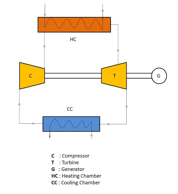
Mian Parts
1. Compressor:
2. Heating chamber:
3. Gas turbine:
4. Generator:
5. Cooling chamber:
Schematic Diagram
- The closed cycle gas turbine works on the principle of Joule’s or Brayton’s cycle
- In this turbine, the gas is compressed isentropically and then passed into the heating chamber. The compressor generally used is of the rotary type.
- The compressed air is heated with the help of some external source and then made to flow over the turbine blades. The turbine used here is of reaction type.
- The gas while flowing over the blades of the turbine, gets expanded. From the turbine the gas is passed to the cooling chamber. Here the gas is cooled at constant pressure with the help of circulating water to its original temperature.
- Now the gas is again made to flow through the compressor to repeat the process.
- Here the same gas is circulated again and again in the working of a closed cycle gas turbine.
Also Read:
- What is Gas Turbine Power Plant?
- Difference between Closed Cycle Gas Turbine and Open Cycle Gas Turbine
- Pelton Turbine Working, Main Parts, Application with Diagram
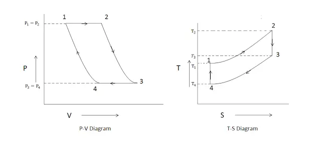
P-V and T-S diagram
The various processes used in this turbine are:
Explanation of P-V and T-S diagram
Process 1-2:
The heating of the gas is done at constant pressure. Here as the pressure is constant, so P1 = P2 and the temperature increases from T1 to T2, the entropy of the gas increases during this process.
Process 2-3:
isentropic expansion of the gas takes place in the turbine. Here the pressure drops from P2 to P3 and volume increases from V2 to V3. In T-S diagram the entropy remains constant but the temperature drops from T3 to T4.
Process 3-4:
Cooling of gas is happen at constant pressure during this process. In P-V diagram the pressure remain constant i.e. P3 = P4 and the volume decreases from V3 to V4.
Process 4-1:
Isentropic compression takes place in the compressor. In P-V diagram the pressure increases from P4 to P1 and volume decreases from V4 to V1 (i.e. gas returns to
its initial volume). In T-S diagram the entropy remains constant (i.e. S4 = S1) and the temperature increases from T4 to T1( T1 is the initial temperature of the gas, it means the gas attains its initial temperature).


