What is Single Point Cutting Tool?
Geometry
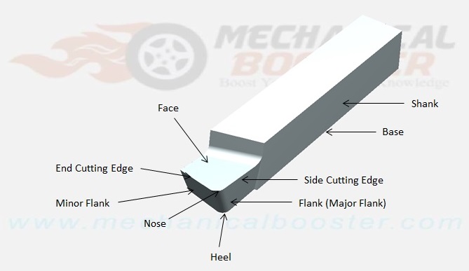
1. Shank:
It is that part of a single point cutting tool which goes into the tool holder. Or in simple language shank is used to hold the tool.
2. Flank:
It is the surface below and adjacent to the cutting edges. There are two flank surfaces, the first one is major flank and the second one is minor flank. The major flank lies below and adjacent to the side cutting edge and the minor flank surface lies below and adjacent to the end cutting edge.
3. Base:
The portion of the shank that lies opposite to the top face of the shank is called base.
4. Face:
It is the top portion of the tool along which chips slide. It is designed in such a way that the chips slide on it in an upward direction.
5. Cutting edge:
The edge on the tool which removes materials from the work piece is called cutting edges. It lies on the face of the tool. The single point cutting tool has two edges and these are
(i) Side cutting edge: The top edge of the major flank is called side cutting edge.
(ii) End cutting edge: The top edge of the minor flank is called end cutting edge.
6. Nose or cutting point:
The intersection point of major cutting edge and minor cutting edge is called nose.
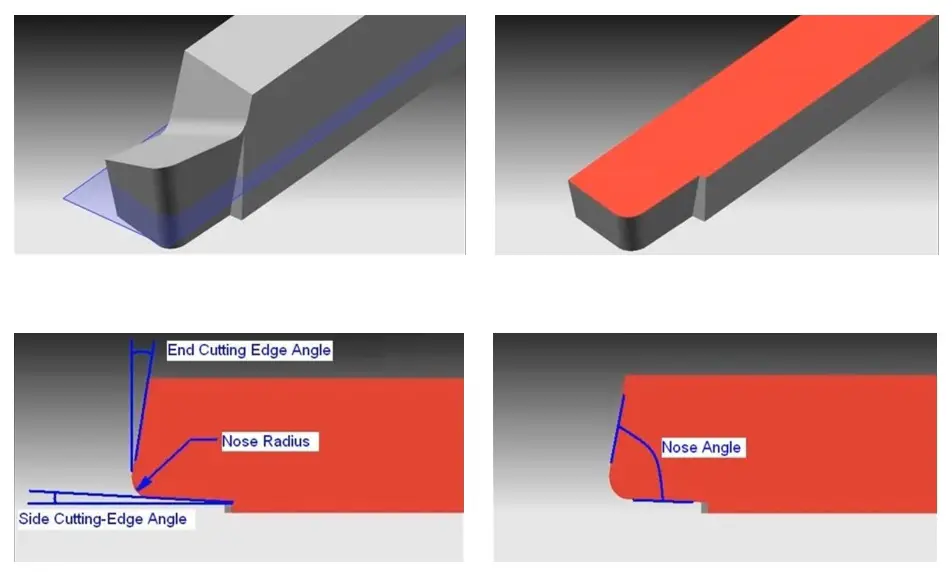
7. Nose radius:
It is the radius of the nose. Nose radius increases the life of the tool and provides better surface finish.
8. Heel:
It is a curved portion and intersection of the base and flank of the tool.
Also Read:
- Types of Milling Cutters Used in Machining Process
- Planer Machine: Definition, Parts, Working, and Operation
- What is Slotter Machine?
Angles of Single Point Cutting Tool
The various angles of the single point cutting tool have great importance. Each angle has its own function and specialty.
1. End Cutting Edge Angle:
The angle formed in between the end cutting edge and a line perpendicular to the shank is called end cutting edge angle.
2. Side Cutting Edge Angle:
The angle formed in between the side cutting edge and a line parallel to the shank.
3. Back Rack Angle:
The angle formed between the tool face and line parallel to the base is called back rake angle.
4. End Relief Angle:
The angle formed between the minor flank and a line normal to the base of the tool is called end relief angle. It is also known as front clearance angle. It avoid the rubbing of the workpiece against tool.
5. Lip Angle/ Wedge Angle:
It is defined as the angle between face and minor flank of the single point cutting tool.

6. Side Rake Angle:
the angle formed between the tool face and a line perpendicular to the shank is called side rake angle.
7. Side Relief Angle:
the angle formed between the major flank surface and plane normal to the base of the tool is called side relief angle. This angle avoids the rubbing between workpiece and flank when the tool is fed longitudinally.

Nomenclature
There are three coordinate systems which are most popular in tool nomenclature. And these are
1. Machine Reference System (MRS)
2. Orthogonal Tool Reference System (ORS) or Orthogonal Rake System
3. Normal Reference System (NRS)
Signature
The shape of a tool is specified in a special sequence and this special sequence is called tool signature. The tool signature is given below
(i) Back rake angle
(ii) Side rake angle
(iii) Clearance or End Relief angle
(iv) Side Relief angle
(v) End cutting edge angle
(vi) Side cutting edge angle
(vii) Nose radius
A typical tool signature of a single point cutting tool is 0-7-6-8-15-16-0.8. Here this tool signature indicates that the tool has 0, 7, 6, 8, 15, 16 degree back rake, side rake, end relief, side relief, end cutting edge, side cutting edge angle and 0.8 mm nose radius.
For Better Explanation Watch the Video Given Below:
This all about the single point cutting tool geometry, angles, nomenclature, and signature. If you find anything missing or wrong than comment us. And if you like this article than don’t forget to share on Facebook and google+.
Got clarified n its perfect!!
What are the application of all angles in single point cutting tool geometry?